


Forensic laboratories are often tasked with reconstructing the evidence when a hit-and-run accident has been reported and one of the vehicles involved has fled the scene.
Residual evidence can range from fragments of glass, headlights, tail lamps, or bits of the bumper, as well as skid marks and paint residues. When a collision between a vehicle and an object or person occurs, paint transfer in the form of smears or chips is quite likely.
Automobile paint is typically a complex mixture of different components applied in several layers. While such complexity makes analysis challenging, it also offers a wealth of potential key information for identifying a vehicle.
Raman microscopy and Fourier transform infrared (FTIR) are some of the principal techniques used to help overcome such challenges and facilitate non-destructive analysis of specific layers within the overall paint structure.
Paint chip analysis starts with the acquisition of spectral data, which can be compared directly to a control sample or used in combination with a database to determine the vehicle’s make, model, and year of manufacture.
The Royal Canadian Mounted Police (RCMP) is responsible for maintaining one such database, the Paint Data Query (PDQ) Database. Access is readily available to participating forensic laboratories that help to maintain and expand the database.
This article focuses on the first step in the analysis process: using FTIR and Raman microscopy to gather spectral data from chips of paint.
Paint Chip Sample Preparation
Using a Thermo Scientific™ Nicolet™ RaptIR™ FTIR Microscope, FTIR data was acquired; whole Raman data was collected with a Thermo Scientific™ DXR3xi Raman Imaging Microscope. The chips of paint were taken from damaged sections of a vehicle; one paint chip originates from a door panel, and the other is from a bumper.
A standard means of mounting samples for cross-sectioning is to embed them in epoxy resin, but there is a risk that analysis can be compromised if the resin penetrates the sample. To prevent this, the paint chips were placed between two sheets of poly(tetrafluoroethylene) (PTFE) while subjected to cross-sectioning.
The cross-sections of paint chips were separated manually from the PTFE before running analysis, and pieces were positioned on a barium fluoride (BaF₂) window. FTIR mapping was performed in transmission mode using a 10 x 10 μm2 aperture, an optimized 15x objective and condenser, and 5 μm steps.
The same samples were used for Raman analysis to maintain consistency, despite thin cross-sections on BaF₂ windows not being necessary. It is important to note that BaF₂ has a Raman peak at 242 cm-1 that can be perceived as a weak peak in some of the spectra. This signal should not be affiliated with the paint chips.
Raman images were acquired using image pixel sizes of 2 μm and 3 μm. Analysis of the spectra was conducted for the main component peaks and compared against commercially accessible libraries by employing methods such as multi-component searching to aid the identification process.
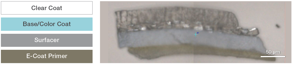
Figure 1. Schematic of a typical four-layer automobile paint sample (left). Video mosaic image of a paint-chip cross-section taken from the door of an automobile (right). Image Credit: Thermo Fisher Scientific – Materials & Structural Analysis
Automobile Paint Composition
While the number of paint chip layers may vary within a sample, samples tend to be comprised of around four layers (Figure 1). The layer directly applied to the metal substrate is an electro-coat primer layer (approx. 17-25 μm thick), which is applied to protect the metal from the environment and act as an adherent surface for the subsequent paint layers.
The next layer is an additional primer, the surfacer layer (approx. 30-35 μm thick), which provides a smooth surface for the next series of paint layers. Then, there is a basecoat or color coat (approximately 10-20 μm thick), which is made up of the primary pigments of the paint. The final layer is a clear protective coat (approx. 30-50 μm thick), which also provides a glossy finish.
One of the main challenges when it comes to analyzing trace paint evidence is that all the layers of paint on the source vehicle will not necessarily be present in paint chips and smears. Additionally, samples from various areas might have different compositions. For example, a paint chip from a bumper may be comprised of bumper materials as well as the paint finish.
FTIR Paint Chip Analysis – Automobile Door
A visible image of the paint-chip cross-section is exhibited in Figure 1. Four layers can be seen in the visual image, which relates to the four layers determined by infrared analysis.
Individual layers were identified using FTIR images of various peak areas after mapping the entire cross-section. Representative spectra from the four layers and associated FTIR images are displayed in Figure 2. The first layer is consistent with a clear acrylic coat and includes polyurethane, melamine (peak at 815 cm-1), and styrene.
The second layer, the base (color) coat, and the clear coat are chemically similar and consist of acrylic, melamine, and styrene.
While they share similarities, and no specific pigment peaks were identified, the spectra still demonstrate differences, primarily in the peak intensities. The spectrum from Layer 1 shows more intense peaks at 1700 cm-1 (polyurethane), 1490 cm-1, 1095 cm-1 (C-O) and 762 cm-1.
The intensity of peaks in the spectrum from Layer 2 increases at 2959 cm-1 (methyl), 1303 cm-1, 1241 cm-1 (ester), 1077 cm-1 (ester) and 731 cm-1. Spectra from the surfacer layer match those with library spectra of an alkyd based on isophthalic acid.
The final electro-coat primer layer is comprised of epoxy and, possibly, polyurethane. Ultimately, results are consistent with what is usually found in automobile paints.
The analysis of the various components in each layer was conducted using commercially available FTIR libraries rather than automobile-paint-specific databases, so while matches are representative, they may not be absolute.
Utilizing databases designed specifically for this type of analysis would enhance identification and could even be used to identify the make, model, and year of the automobile.
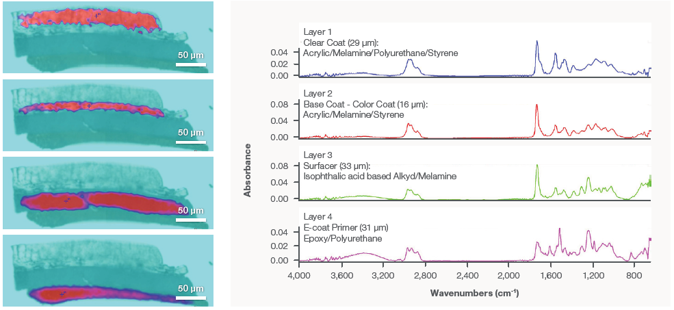
Figure 2. Representative FTIR spectra from the four identified layers in the door paint-chip cross-section. Infrared images are generated from peak areas associated with the various layers, which are then superimposed on the video images. The red areas show the location of the various layers. The infrared image covers an area of 370 x 140 μm2 using a 10 x 10 μm2 aperture and 5 μm steps. Image Credit: Thermo Fisher Scientific – Materials & Structural Analysis
FTIR Paint Chip Analysis – Bumper
A video image of a bumper paint-chip cross-section is displayed in Figure 3; at least three layers are clearly distinguishable.
Infrared images of the cross-section verified three distinct layers (Figure 4). The outer layer is a clear coat that is likely to be a polyurethane material with acrylic, which, when compared with clear coat spectra from a commercial forensic library, demonstrated a match.
While the spectrum from the base (color) coat is extremely similar to the clear coat, it was still unique enough to be distinguished from the outer layer. There are considerable differences in relative peak intensities.
The third layer is potentially the bumper material itself and is comprised of polypropylene as well as what appears to be talc. Talc may be used as a reinforcing filler with polypropylene to enhance a material’s structural properties.
The two outer layers are both consistent with paint layers used in automobile paint, but no specific pigment peaks were determined in the base coat layer.
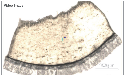
Figure 3. Video mosaic image of a paint-chip cross-section taken from the bumper of an automobile. Image Credit: Thermo Fisher Scientific – Materials & Structural Analysis
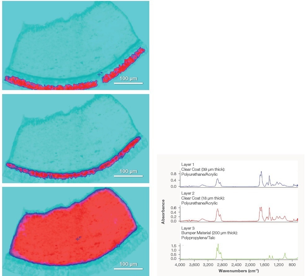
Figure 4. Representative FTIR spectra from the three identified layers in the bumper paint-chip cross-section. Infrared images are generated from peak areas associated with the various layers, which are then superimposed on the video images. The red areas show the location of the various layers. The infrared image covers an area of 535 x 360 μm2 using a 10 x 10 μm2 aperture and 5 μm steps. Image Credit: Thermo Fisher Scientific – Materials & Structural Analysis
Raman Microscopy
A Raman imaging microscope was used to analyze a sequence of cross-sections to acquire additional information on the samples. The Raman analysis, however, was further complicated by fluorescence from the samples. A number of different laser sources (455 nm, 532 nm, and 785 nm) were tested to assess the balance between fluorescence and Raman signal intensity.
For the door paint chip analysis, a 455 nm laser offered the best results; while there was still fluorescence present, it could be offset using a baseline correction. This approach, however, was unsuccessful with the epoxy layer because the extremity of the fluorescence was too much, and the material was vulnerable to laser damage.
While some lasers were better suited than others, none were a practical choice for the epoxy layer’s analysis. A 532 nm laser was applied for the Raman analysis of the bumper paint-chip cross-section. There were still fluorescence contributions, but these were tackled with a baseline correction.
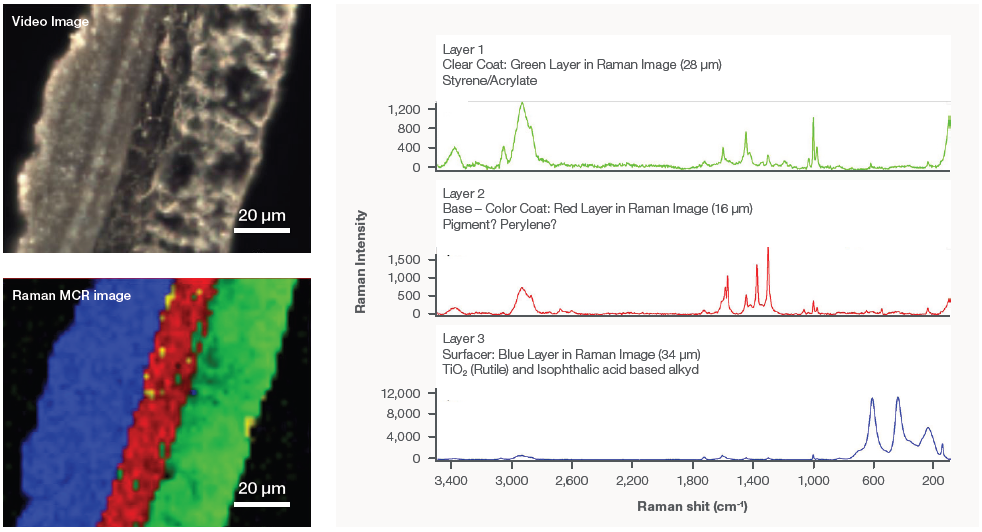
Figure 5. Representative Raman spectra from the first three layers of the door paint-chip sample (right). The fourth (epoxy) layer was lost during sample preparation. The spectra have been baseline corrected to remove fluorescence contributions and were collected using a 455 nm laser. An area 116 x 100 μm2 was imaged using a pixel size of 2 μm. Video mosaic image of the cross-section (top left). Raman multivariate curve resolution (MCR) image of the cross-section (bottom left). Image Credit: Thermo Fisher Scientific – Materials & Structural Analysis
Raman Paint Chip Analysis – Automobile Door
The Raman imaging analysis of the door paint-chip cross-section is shown in Figure 5; this sample did not reveal the epoxy layer as it was lost during preparation. However, since it had been determined that Raman analysis of the epoxy layer was problematic, this was not considered to be an issue.
The presence of styrene was much more widespread in the Raman spectra from Layer 1, while the carbonyl peaks’ intensity was much lower than the infrared spectra. There was a considerable difference in the spectra from the first and second layers in the Raman analysis compared to FTIR.
The closest Raman match to the base-color coat was perylene; while it was not an exact match, it is widely known derivatives of perylene are used for pigments in automobile paint, so it could denote the pigment in the color layer.
Surface layer spectra were consistent with an isophthalic acid base alkyd; however, they also revealed that titanium dioxide (TiO₂, rutile) was present in the sample, which can sometimes be tricky to observe with FTIR, depending on the spectral cutoff.

Figure 6. Representative Raman spectra from the bumper paint-chip sample (right). The spectra have been baseline corrected to remove fluorescence contributions and were collected using a 532 nm laser. An area 195 x 420 μm2 was imaged using a pixel size of 3 μm. Video mosaic image of the cross-section (top left). Raman MCR image of a portion of the cross-section (bottom left). Image Credit: Thermo Fisher Scientific – Materials & Structural Analysis
Raman Paint Chip Analysis – Bumper
Figure 6 reveals the Raman results for the bumper paint-chip cross-section. An additional layer (Layer 3) was exposed, which was not previously detected with FTIR.
The closest match for the outer layer was a styrene-ethylene-butadiene copolymer, but there was also an indication of an additional unknown component illustrated by a small carbonyl peak that could not be accounted for.
The spectrum from the base-color coat is supposably representative of a pigment component because, to some extent, the spectrum matched phthalocyanine compounds that are used as pigments.
The layer that was previously unknown is quite thin (5 µm) and is comprised of carbon and rutile in part. Due to the thickness of the layer, and the fact that is difficult to detect TiO₂ and carbon using FTIR, it is not surprising that it was not detected by the infrared analysis.
In agreement with the FTIR results, the fourth layer (bumper material) was determined to be polypropylene, but Raman analysis also revealed the presence of some carbon. While the presence of the talc seen with FITR cannot be excluded, exact identification was not possible as the corresponding Raman peaks were too small.
Conclusions
Automobile paints are intricate mixtures of components, and while this can reveal a wealth of identifying information, it also makes analysis a significant challenge. Paint chip evidence can be probed effectively utilizing a Nicolet RaptIR FTIR Microscope.
FTIR is a non-destructive analytical technique that provides practical information about the different layers and components in automobile paints.
This article discussed the spectral analysis of paint chip layers, but closer inspection of the results, either by direct comparison with a suspected automobile or dedicated spectral database, could offer even more precise information to match the evidence with its source.
Raman analysis with the DXR3xi Raman Imaging Microscope delivered additional information on the paint chip samples. While both FTIR and Raman are vibrational spectroscopy technologies, this article outlines how they can be applied to identify the various components of paints.
In combination, these techniques offer a more comprehensive and complementary view of the samples. The extent of information these techniques can provide relative to the individual paint layers makes them valuable resources for the complex task of forensic paint analysis.

This information has been sourced, reviewed and adapted from materials provided by Thermo Fisher Scientific – Materials & Structural Analysis.
For more information on this source, please visit Thermo Fisher Scientific – Materials & Structural Analysis.


